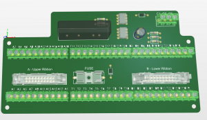
Making the layout of boards means choosing the best configuration of space utilization. An improperly placed or improperly placed component can make the board difficult or unworkable, so board layout is such an important step. With the quick turn PCB you can have the best option now. Some software such as Altium Designer, EAGLE PCB and Orcad, among others are great allies, but you need to know the basics. To assist you in this work, we separate the process into steps, which must be followed:
Choose good materials

The first step in a mounting board is choosing the materials to use on it. It is no use working exhaustively on the layout of the plates if the quality of the raw material is questionable or vulnerable. There is no right answer regarding the brand or model, as each case is a case. Just consider what a good board needs: resist the temperature well, have good dielectric strength, resist vibration well, and have good mechanical strength.
Evaluate component size
Board components come in various sizes to meet different needs. Thus, details such as terminal spacing, for example, are different for each of them. Therefore, before designing the plate layout, you need to consider sizes and spacings to make sure there are no problems.
Respect the width of the trails
The general rule is that in a good board layout, the width of the tracks depends on the electrical current, ie the more Amps the current has, the wider the track should be (the recommended ratio is 1mm for each Amper). Other factors can also influence the width of the tracks such as whether or not connecting the relays to the output terminals, for example.
Take noise sources into account
When connecting to other circuits, there may be some kind of electrical noise. This is because circuits connect with power devices as well as ground, becoming a kind of medium to the outside, and that’s where the noise comes from. The sources can be diverse, in addition to wired conduction, can also come from cell phones, radio and TV waves, fluorescent lamps, etc.
Component Positioning
An article on plate layout published in 2005 by Professor Anderson Royes Terroso, coordinator of the PUCRS Electronics Teaching Laboratory – LEP, explores and illustrates with photos how component placement can influence plate layout. You can access the full article, available on the internet, but we highlight some aspects covered by it:
Crystal – Crystal positioning is important in many cases. It should be very close to the capacitor and pins as the crystal will be connected to them.
Filter Capacitors – Similarly, filter capacitors should be close to the pins that are connected, or there is a chance of noise.
Reset circuit – it, as well as the components that are part of it, should also be close to the CPU.
RS232 Serial Port – Caution, in this case, is not to place it overturned The four pins should be facing the edge of the card. Components related to it should also be close.
